
This guide is based on the tutorial video available here. Special thanks to Martins Assembly Haven for creating such a detailed and carefully made assembly walkthrough.
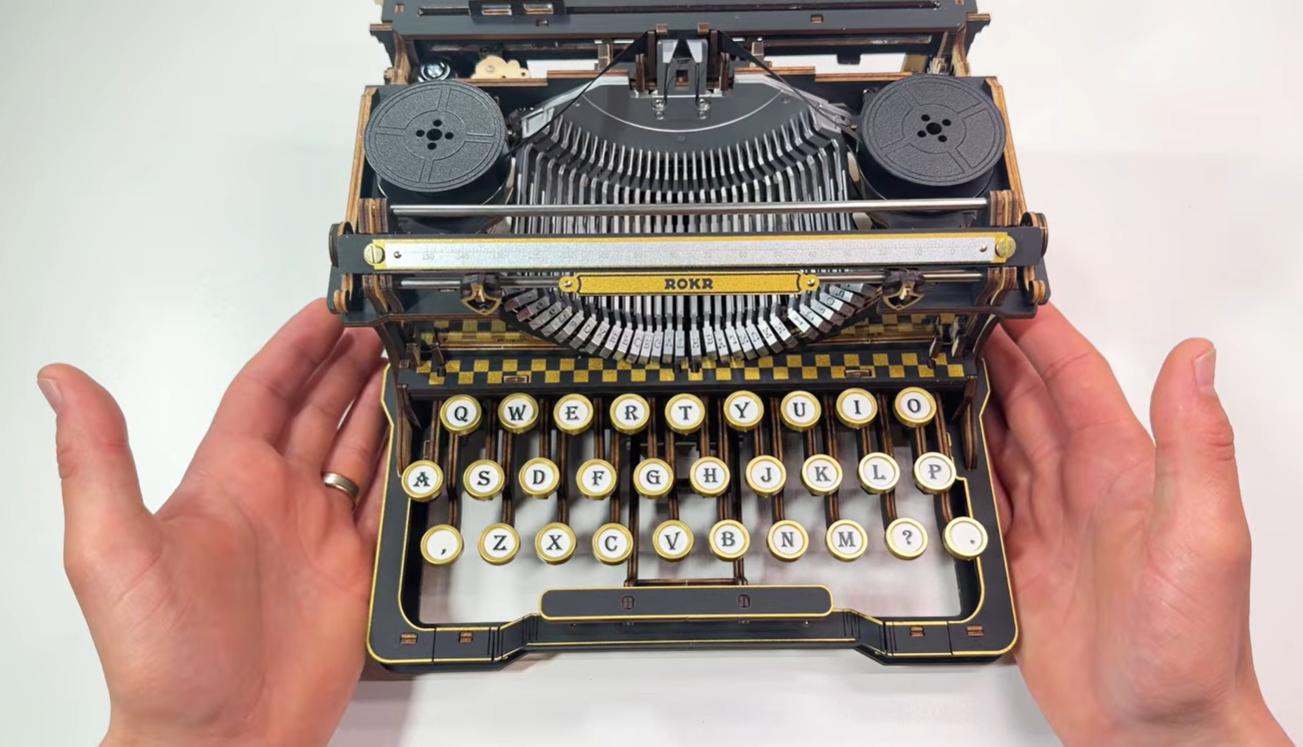
The ROKR Mechanical Typewriter LK703B is a 320-piece wood-and-metal model that turns a hands-on puzzle build into a working vintage-style typewriter. Once assembled, its keys, typebars, ink ribbon, carriage, feed knobs, and bell work together to make real letter impressions on paper.
This is one of ROKR's most demanding 3D wooden puzzles. It is rated as a 6-star challenge, and the build asks for close reading, careful alignment, and repeated testing. Treat it less like a decorative model and more like a small machine you are calibrating piece by piece.
Before You Build
The LK703B can be deeply rewarding, but it is not a quick weekend puzzle. Before you punch out the first parts, set your expectations around patience, order, and mechanical testing.
- Difficulty level This is a master-level build, so beginners may want to complete a simpler ROKR kit first.
- Build time Plan for at least 11 to 12 hours and split the work across several calm sessions.
- Ink ribbon Handle the ribbon gently, and do not pull, stretch, or rewind it before the carriage mechanism is ready.
- Mechanism checks Test each moving section before hiding it behind later layers.
- Common mistakes Over-tightened screws and skipped motion checks can lead to misaligned typebars or a stiff carriage.
Unboxing, Tools, and Workspace
The kit includes a user letter with troubleshooting reminders, a 54-page instruction manual, wooden and plastic sheets in several thicknesses, metal typebars, bar wires, shafts, sleeves, a bell, acrylic parts, steel pipes, spring plates, wire clips, key caps, screws, the ink ribbon, and selected spare parts.
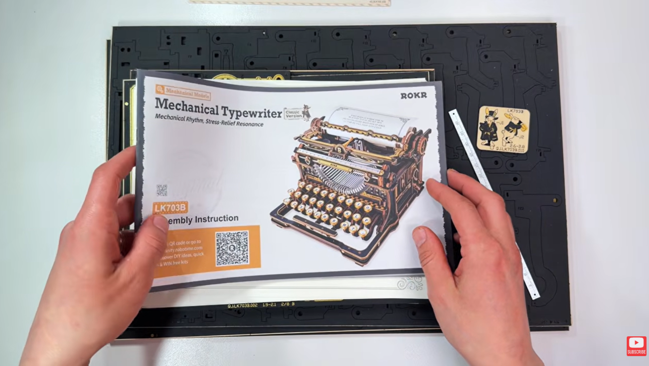
The included or recommended tools may include a flat punch-out tool, tweezers, screwdrivers, sandpaper, a file, a plastic clipper, and wax sticks. Some territories do not allow wax to be shipped with the kit; ordinary candle wax can be used as a substitute when the manual calls for wax.
- Model
- ROKR Mechanical Typewriter LK703B, Classic Version
- Pieces
- 320 pieces
- Challenge
- 6-star, master-level mechanical build
- Core payoff
- A functional vintage-style typewriter with moving keys, typebars, ribbon, carriage, paper feed, and bell
Before assembly, inventory the sheets and small hardware. If anything is missing or broken, follow the service instructions in the kit documentation; the ROKR part replacement page may also help with support routing.
Choose a bright work surface and line it with a white sheet so tiny dark pieces, screws, springs, and gear teeth are easier to spot. A sectioned container, small tray, or egg carton is useful for sorting parts before each sub-assembly.
Assembly Roadmap
You will build five functional zones. Understanding the role of each one makes the detailed steps easier to follow.
| Section | What it does | Main build risk |
|---|---|---|
| Base chassis | Creates the lower platform and side frame that support every later mechanism. | A warped or uneven base can make moving parts feel stiff later. |
| Typebar mechanism | Holds the lettered arms and shared pivot system that rise when keys are pressed. | Wrong rod placement or crossed wires can stop letters from lifting cleanly. |
| Keyboard | Combines key caps, stems, return springs, and wire hooks into the typing input. | Misaligned keys can stick or fail to return. |
| Carriage assembly | Builds the platen roller, paper feed, ribbon route, spools, guide ruler, and bell area. | Insufficient sanding or waxing can keep the carriage from sliding smoothly. |
| External shell and testing | Adds decorative panels and final working checks. | Skipping test typing can hide ribbon, carriage, or key alignment issues. |
Only punch out the parts you need for the current section. This keeps the workspace manageable and reduces the chance of mixing similar pieces. Use the wooden tool to press parts out from the reverse side, then lightly sand burrs where the manual recommends it.
Step-by-Step Assembly
The following sequence follows the main mechanical logic of the LK703B. Use it as a guided companion while the printed manual confirms every exact part orientation.
Base Chassis
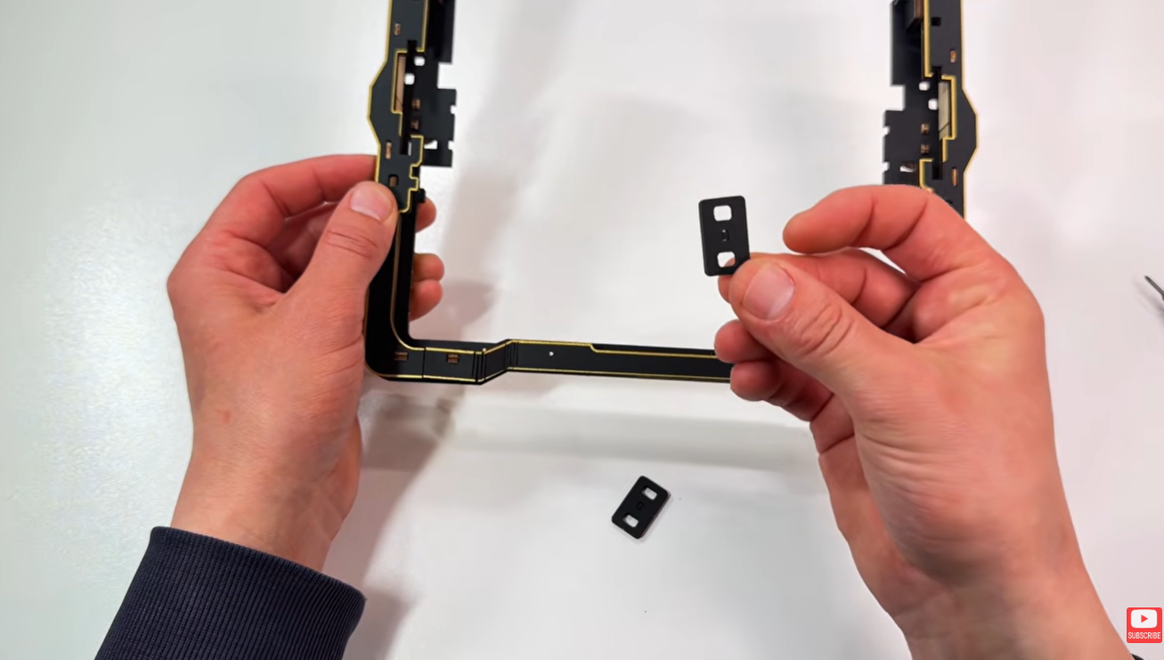
- Start with G1B. Insert G26 into the two front holes with the pattern facing the board and the colored side facing you. Add the two D2 pieces from the back into the bottom holes of G26.
- Build two matching feet. Begin with D12, insert the D15 short legs, add D13, then D14, and attach the P32 rubber anti-slip stickers from bag 3 to the bottoms. Seat the completed feet on both sides of the base.
- Add B3 and B4. For B3, place the back leg first, leave it slightly loose, bend the piece forward, and pop the front hole into place. Only press fully flush once both ends are seated. Repeat this controlled bending motion on both sides.
- Thread a P14 screw from bag 2 through the colored side of G2B without driving it all the way through. Fit G2B into the right-hand front holes, then mirror the step with G2E on the left side.
- Add the B23 and B22 pieces into the rectangular side holes. Insert four B20 pieces with the gold color facing outward.
- Finish the base with two P16 long screws from bag 2 through the G39 pieces. Add two C3 pieces to lock the base and upper layer together. Check that the chassis sits flat without wobbling before setting it aside.
Typebar Mechanism
- Assemble F5, F46, and F4 onto the two F36 pieces. Place F5 in the leftmost hole of F36, add F46 in the next hole, join the two F36 pieces, and seat F4 into the two front bottom legs.
- Place H11 between two H16 pieces. Thread a P8 rod through the bottom-right hole with a P49 sleeve pressed flush on one end. Set spring P25 from bag 3 between the H16 pieces, push the rod through, and add the second sleeve.
- Thread two P11 long rods from bag 1 through the assembly with sleeves flush at both ends. Make sure the spring connects to both rods. Test for a springy response before continuing.
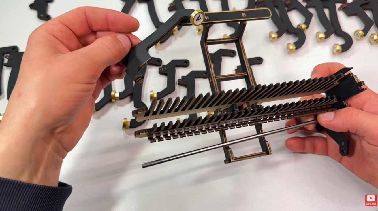
- Fit G18 onto the two back legs of the base. Add G16 into the top hole on the right side, then build the H20-H21 assembly. Mount the plastic tooth pieces with C3 in the center, using P13 screws through the front of the plastic.
- Mount the comb-like H21 over the train sub-assembly, then place the full assembly onto the G18 support through the two larger holes.
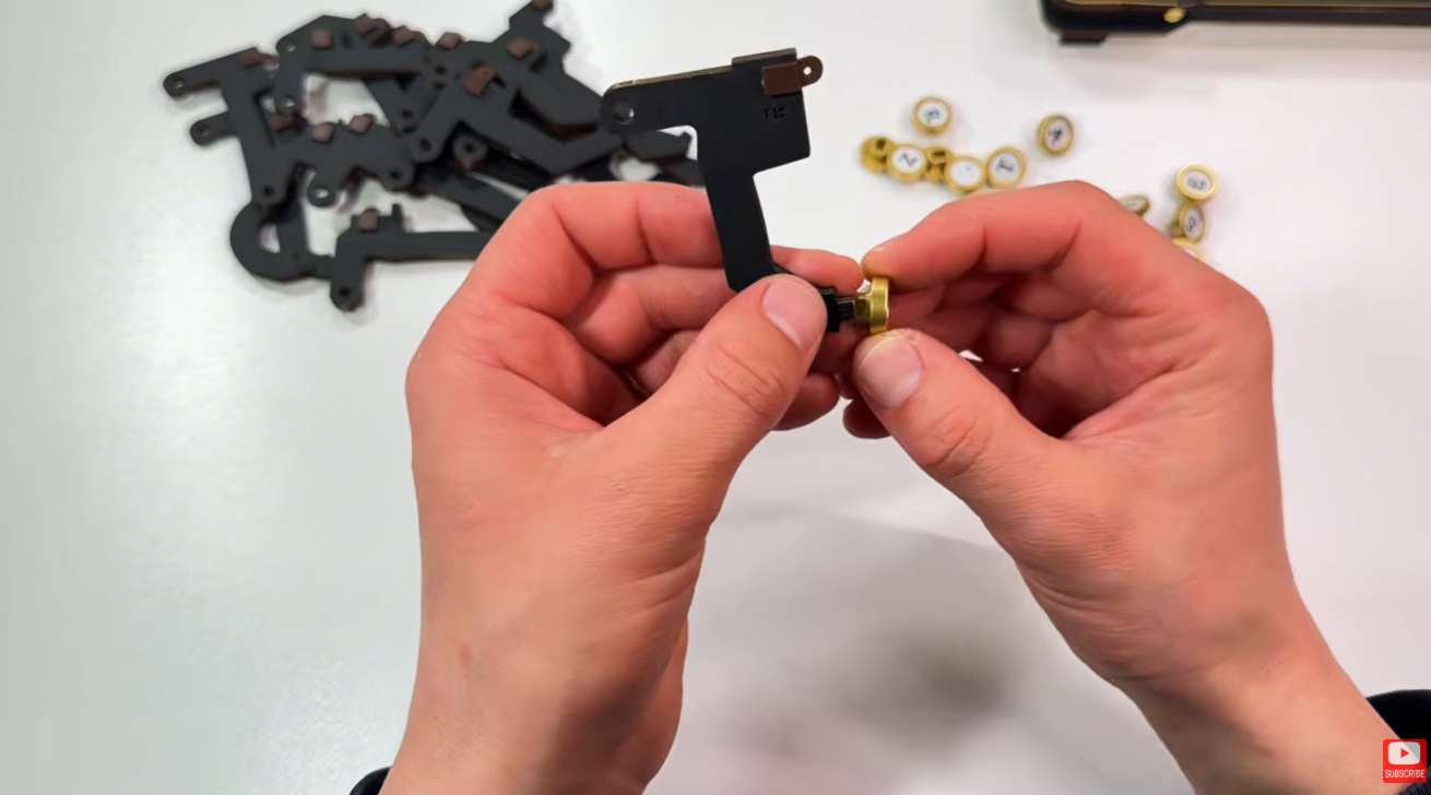
- Prepare the 15 wooden key pieces from the F board: F6, F7, F8, F10 to F20, and F22. For each one, insert the P42 plastic connector from the left-hand side, with its protruding leg going through the small hole.
- Attach the P40 key caps. Clip one leg from the sprue, twist for a clean edge, match each engraved letter to the correct key cap, and press the cap on so the letter reads correctly when the piece is upright. Sort the keys in the order shown in the manual.
- Build the C part with F37 by holding it with the three different-sized holes on the left and the circular hole facing down. Insert A2, add A8 with its hole facing up, and fasten with a P13 screw flush at the back.
- For the spring on the C part, thread another P13 screw through the ring of spring B25 from bag 3 and install it in the front hole. Build the D part with F39 in the mirrored orientation, with the spring-and-screw assembly entering from the back side.
- Find the longest metal rod, P36. Place the F37 C-part assembly in position with the spring facing inward toward the shaft, then begin threading the rod through the bottom hole.
- Hang the keycap assemblies on the rod one by one in the manual's sequence. The teeth on the H20 assembly show where each letter belongs. Keep a finger on the shaft so it does not slide out while you work.
- Add the F39 D-part assembly to the other end to secure the rod. The P42 connectors should now act as return springs, allowing the keys to bounce back when pressed.
- Insert the top hole of H2 on the right side into G16, with only the top leg entering and the rest facing downward. Hold the keyboard assembly gently, keep the rod from sliding, and align the G16 hole with the rod end and wooden legs. Repeat on the other side.
Keyboard Assembly
- Follow the H8 order shown in the manual: C17B, C17A, C17B, C17A. The longer leg faces you and enters the matching holes while the back hole stays at the rear.
- Add F38 to the four holes at the front of H8. Press the P111 50 mm rod from bag 1 through the front holes with one P49 sleeve flush on the starting end. Add the second sleeve on the exit end, leaving about 1 cm from the shaft end on both sides.
- Use one of the remaining P37 208 mm metal rods. At the back of the keyboard, move the spring-loaded pieces forward until two holes appear. Push the shaft through those holes with tweezers, placing it between the teeth and the keys.
- Once the shaft is seated, the keys should no longer fall all the way back. If you hear rubbing when pressing keys, wax the slots as directed.
- Place H7 onto the four middle holes of the keyboard. Push the spring-loaded sliding piece back while pressing H7 into place.
- Insert D4 through the bottom of H6, then mount that piece on the keyboard with the two middle teeth passing through the corresponding middle holes.
- Turn the base and keyboard so their backs face you. Slot the longer keyboard leg into the matching rear slot on the base, then repeat on the other side. Push until the rear legs fall into the holes. Slight side-to-side adjustment may be needed.
- From the back, press the keys and confirm that the movement looks synchronized, almost like piano keys moving together.
- Hook the spring ends from the C-D assembly onto the protruding screw heads. Use tweezers to open each ring only a little, then mount D6 onto the two longer rear legs of H6, aligning the two center holes with the longer center legs.
- Hook each P42 connector wire into the matching hole in the typebar mechanism above it. Tug gently to confirm the letter match, then lift the corresponding typebar arm while squeezing the wire into place with small long-nose pliers.
- Work in sequence without skipping letters, and set the wires back gently so they do not cross. Remove the H5 auxiliary tool piece. Pressing a key should now lift the matching typebar arm.
Carriage Assembly
- Build the C6-C5-C7 assembly with C5 in the middle. Thread a P10 40 mm shaft from bag 1 through it and press the sleeve flush by using two tools from opposite ends. Mount this unit on the four small center pegs.
- Thread the rod through the first two holes, then through the remaining two holes of the assembly. Add the second sleeve flush on the exit end. The arrows on C6 and C7 should point upward.
- Remove G18. Insert C1 at the front with its single center leg and colored side facing you, then add the C2 pieces on both sides. Mount G27 onto the three front legs and insert the B1 pieces into the holes.
- Add G37A on the left and G19A on the right. Pop the first hole of each C3 in slightly, align the second hole, then press both in together. Repeat the mirrored side.
- Mount the escapement mechanism with its teeth facing the keyboard. The two bottom legs pass through the large gaps at the bottom of the model. From the back, add two C12 pieces to lock those lower legs.
- Thread a second P10 40 mm rod with sleeves through the bottom mechanism hole, through the moving piece, and out the other side.
- From the rear, place G32 at the top right and G29 at the lower right, with G29's longer leg pointing right. Mirror this with G31 at the top left and G30 at the lower left. Each side piece must sit in front of F47. Pressing the space bar should now move the rear mechanism.
- Take two H1 pieces and connect an H3 to the shorter end of each one with the colored side facing up. Thread the P12 85 mm rod through with one P49 sleeve, then mount gear D32 and E13. The square-hole gears go on the H3 pieces, and the wider-hole gear goes where the wider legs are.
- Mount H39 on the right-hand side while guiding the gear shaft into place. The sleeve end of the rod enters the specified inner hole, and the other end passes through the far side wall. Align the gear teeth with the adjacent gears.
- Prepare the P38 ink ribbon cartridges. Before mounting, wind most of the ribbon from the right spool to the left spool by hand, keeping the ribbon flat and unfolded.
- Mount both spools on their posts. Route the ribbon across the front of the model, not the back, and pass it between the front guide and tooth guide on each side. Tighten the ribbon by winding the left spool slightly. The ribbon should be taut, not stretched.
- Test by pressing a key firmly. The ribbon should rise and fall, and the spool should turn slightly.
- Sand and wax the carriage rail contact areas carefully. Add two C9 and two C10 pieces, placing one C9 and one C10 on each side of the H40 pieces.
- Build the platen roller assembly with H45 and E5. Add C24A and C24B on the left and right, then thread P31 rubber tubes onto P11 50 mm shafts.
- Pair each D24 with a C19, with D24 entering the middle hole. Clip each C18 onto the end of the assembly, followed by the C19-D24 unit on both sides. Confirm that the rubber roller turns freely.
- Add C22 with its two small legs facing up and the plain side facing away. It bridges the roller assemblies by entering each set of holes from one end to the other.
- Press a P49 sleeve on each side of two P7 15 mm shafts. Flip the carriage over and identify the two holes. Place the black P26 spring from bag 3 in the middle before threading the shaft through. Hook or push the spring ring onto the shaft, thread fully, and press the exit sleeve flush. The assembly should spring back freely when pulled.
- Build the platen drum by sliding H44 through H32 with H44's groove facing upward so P39 can slide over it later. Push H44 to the center of H32, then add H31 by squeezing it over H32 and through H44.
- Wax the edges of H30 and the sides of the two H29 pieces. Mount the H29 pieces, then add H30 in front of them.
- Slide the P39 plastic tube over the assembly, aligning the internal grooves with H44 and H31. Rotate slowly while pushing until it drops into alignment. Leave a small gap between the tube end and wooden pieces so everything can move freely.
- Add C26 to the tube, aligning the grooves. Add D33 to the end, then H33 and H34 on the sides after waxing them. Apply the P50 sticker to P51 before mounting.
- For the paper guide, insert black spring P30 into the bottom hole of E8. Thread a screw through B18 and mount E7 on that screw. Push the spring leg under E7 while adding the second front screw and the third bottom screw. E7 should snap down and bounce back.
- Mount E21 on the other side and push out the extra inner parts from B18 and B21.
- Insert A10 through the single hole in A26 until flush, then mount it onto E9 gently with the tool. On E15, insert E17 into the two smaller left-hand holes, then insert two E16 pieces into the two larger right-hand holes before mounting the full E9 assembly.
- Mount E6 into the rear hole of the carriage and lock it with E14 at the front. For the right side, mount E19 with the same logic in mirrored orientation and lock it with E14 at the back. Wax the inside of holes that hold moving wooden parts.
- Mount D5 at the back top of the drum. Add D30 on the left and D31 on the right. D5 may feel loose while you work around it.
- Place the two H41 pieces through the rear rectangular holes where the spring sits, with the leg squeezing them together. Add G24 pieces on the outer sides, install G21 at the top front, and add G22 or G23 on each side.
- Mount the decorative D1 pieces with the gold color facing outward on one side. Drive two P13 6 mm screws from bag 2 upward through the bottom of the carriage into the locking holes.
- For the paper guide ruler, combine B26 and B25, then insert five D39 pieces into the five bottom holes. Thread B2 through the three holes while keeping both sides above the D39 pieces. Lock it with C21 at the front top, add the side pieces, and mount the ruler assembly on the back two holes of the carriage.
- Build the feed knobs by locking D43 into the larger middle hole of D42. Add B14 to the adjacent hole, pop the side on, and press the small golden ROKR badge into the center of D42. Build the second knob the same way.
- Mount B5 and B6 into the two-hole slots on each side of the carriage front, working alternately so the structure seats evenly.
- Mount the carriage from the back of the typewriter. The large lower gap slots over the rear chassis rail. Tilt the carriage slightly, push it forward and down gently, and lock it with G35. Check that the "R" plate on the front of the carriage sits correctly on the metal rod or tube.
External Shells and Testing
- Place the two rabbit figures into the side holes near the carriage steps. Keep them centered and clear of moving gears.
- Move the carriage all the way to the right before loading paper. Keep it level, grip the right side, and slide it to the right without twisting.
- Feed a standard-weight A4 sheet, around 75 to 80 gsm, from the top front of the platen. Turn both feed knobs to pull the paper through. If needed, give the paper a gentle starting push until the rollers catch.
- Use the pressure plate to hold the paper after it feeds through. Straighten skew by gently pulling the paper edge before it is fully gripped.
- Type with a firm, quick, straight-down keystroke. Do not press lightly or at an angle. The carriage should advance one character per key press.
- When the bell rings, use the line-feed lever to advance to the next line and return the carriage as directed by the manual.
Testing Checklist
Before calling the build complete, check each working system in a slow, visible way.
- Keys Each key should return after pressing and should lift the matching typebar arm.
- Wires Connector wires should sit in the correct holes without crossing or pulling sideways.
- Ribbon The ribbon should rise with a firm key press and settle back without folding.
- Spools The ribbon spool should turn slightly during typing without becoming too tight.
- Carriage The carriage should slide level, advance character by character, and return without scraping.
- Paper feed The platen and feed knobs should pull paper through evenly and hold it straight enough for test typing.
If you enjoy builds where motion, alignment, and patience matter, the Mechanical Typewriter belongs in the same world as ROKR's more demanding mechanical models. For a broader difficulty comparison, see this guide to challenging ROKR builds.
Assembly Review
The ROKR Mechanical Typewriter LK703B is less like assembling a simple display puzzle and more like building a compact mechanical system. The most satisfying moments come when a hidden alignment choice suddenly becomes visible: a key rises correctly, the ribbon moves, the carriage advances, or the bell confirms the end of a line.
That also means the build is unforgiving. The margin for error is small, and several steps depend on earlier parts being seated cleanly. The kit rewards builders who pause to test, wax carefully, and fix friction before moving on.
Once complete, the payoff is unusually strong. You do not just display the finished typewriter; you can load paper, press the keys, and see the mechanism convert your hands-on work into typed marks. For hobbyists who enjoy calibration as much as construction, LK703B is a memorable and highly rewarding challenge.
FAQ
Does the ROKR Mechanical Typewriter really type?
Yes. When built and adjusted correctly, LK703B uses moving keys, typebars, an ink ribbon, and paper feed parts to make real impressions on paper.
Is LK703B good for beginners?
It is better for experienced or very patient builders. Newer builders may want to start with a simpler 3D wooden puzzle before attempting a 6-star mechanical kit.
How long does the build take?
Plan for at least 11 to 12 hours. The best pace is several focused sessions with time for testing and adjustment.
What is the most important build tip?
Test each mechanism before continuing. Small problems with rods, wires, ribbon tension, or carriage friction are easier to fix while the section is still open.