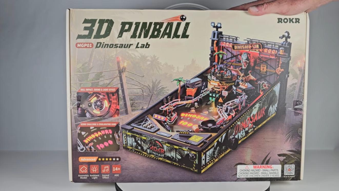
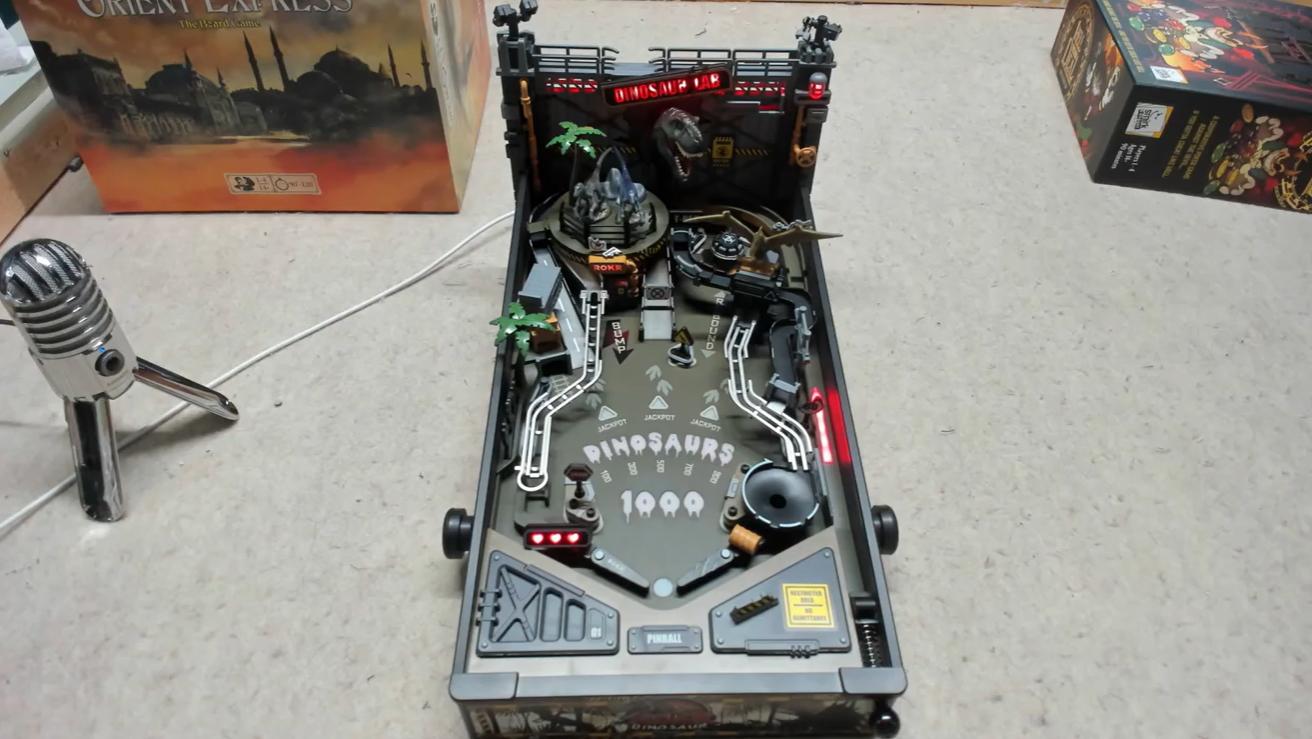
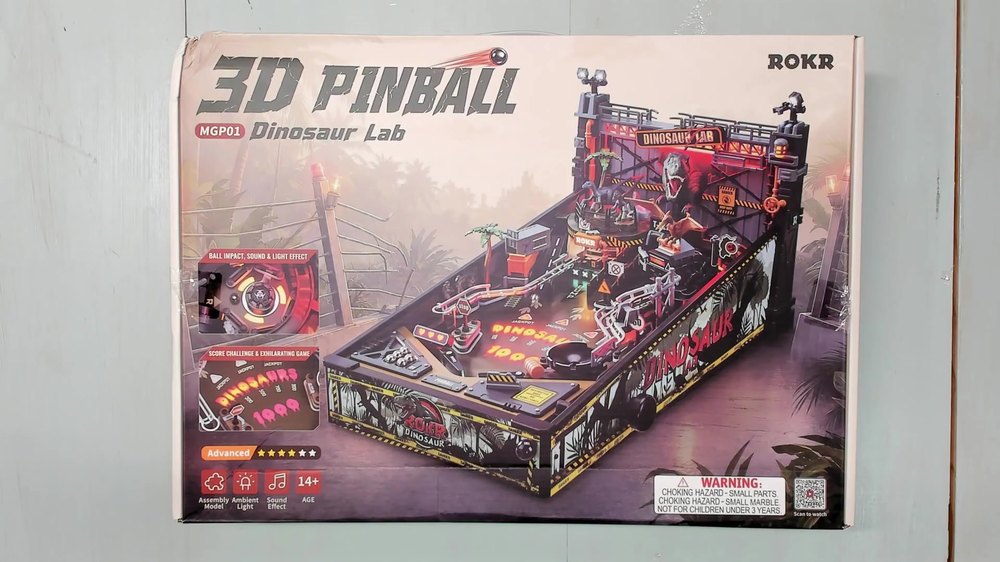
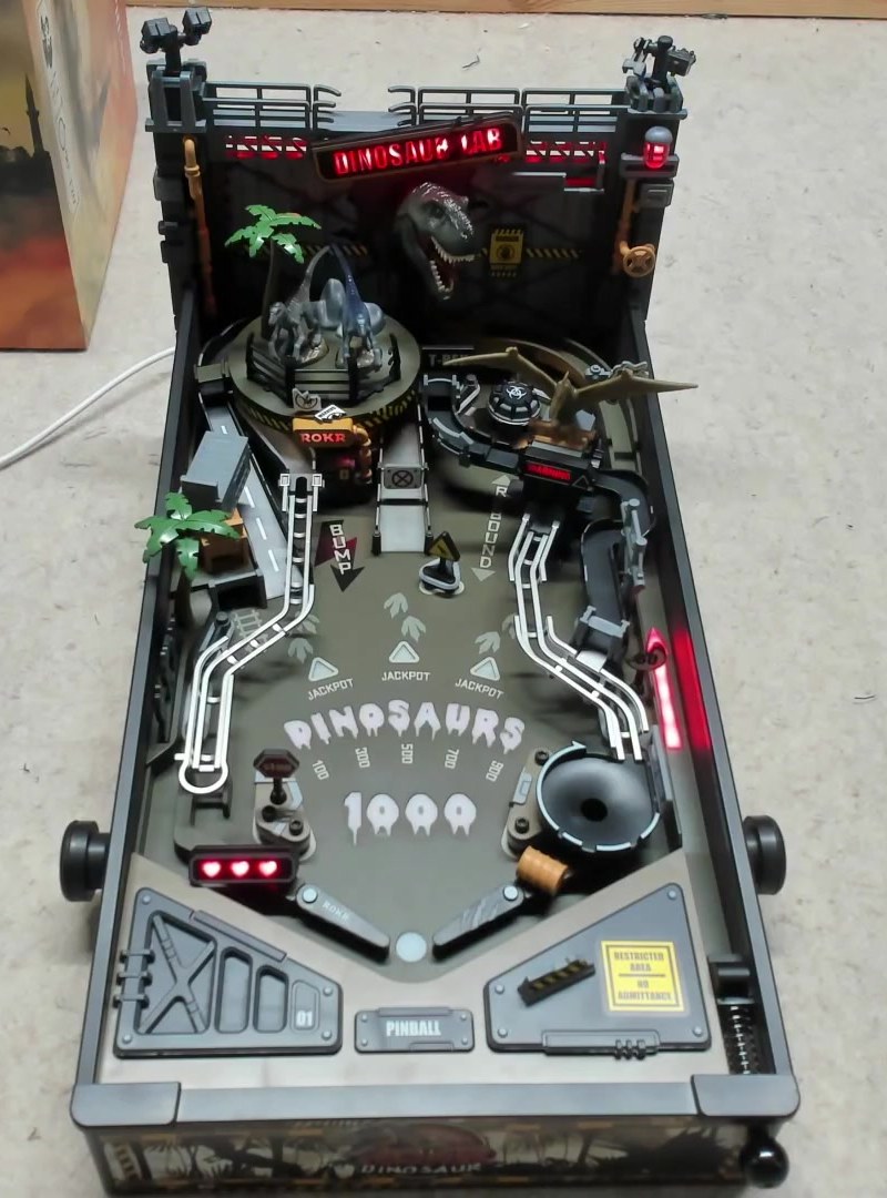
This assembly guide covers the ROKR Dinosaur Lab MGP01, a tabletop pinball machine with 319 plastic and wood pieces. This interactive DIY kit is recommended for builders aged 14 and up. Special thanks to Clint Conner for creating such a detailed and carefully made assembly walkthrough.
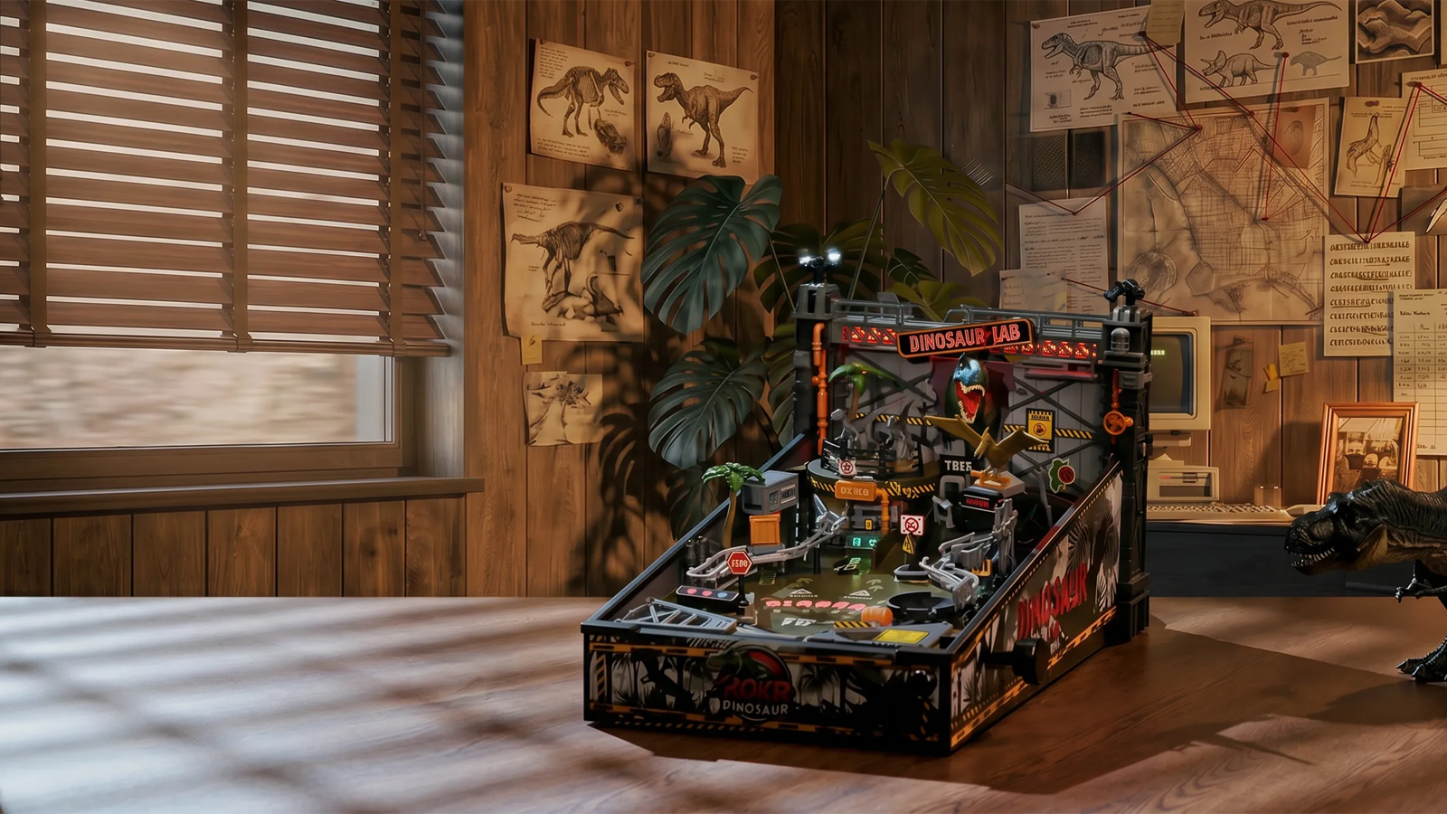
If you find a missing, incorrect, duplicated, or damaged part, pause the relevant step and use the Dinosaur Lab Pinball Support Guide before continuing.
Build photos in this guide come from Clint Conner’s Dinosaur Lab build series on YouTube, used with permission.
Tips and Reminders
Before we start, here are some helpful reminders:
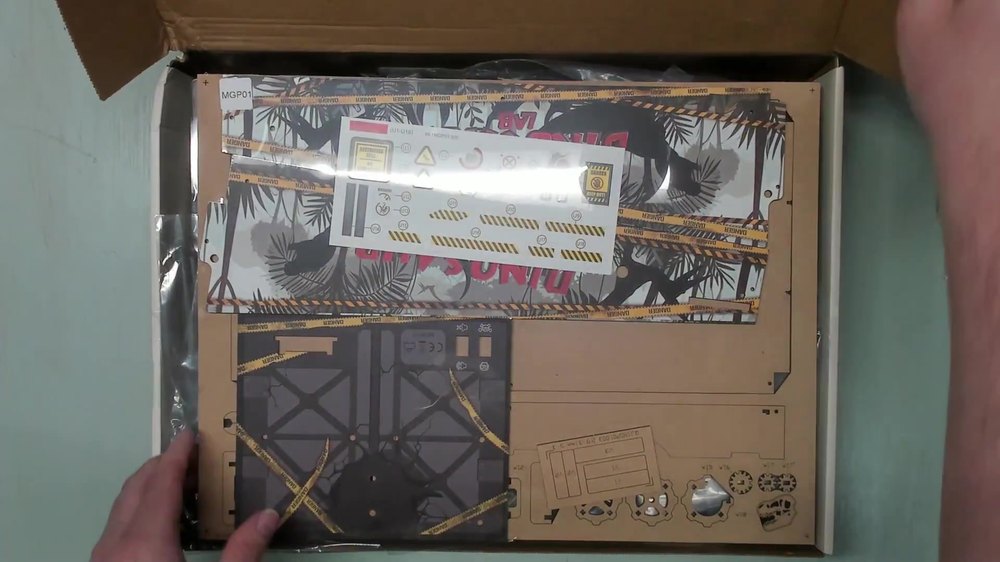
- Don’t open every bag at once when you start building your kit. Remove only the pieces you need from the sprues and keep a handy container on your desk to avoid losing small loose parts.
- Some parts look similar, but aren’t interchangeable; for example, P38, P39, and P40. Make sure to identify them correctly using the illustrated manual.
- Some territories don’t allow grease to pass through customs. You may use lithium grease for lubricating plastic parts when necessary.
- Most instances of parts breaking or not moving are caused by overtightening screws. Never twist past the part’s thread to avoid damaging pieces.
- Leftover parts are normal. ROKR always adds some spares to help you out.
- The power supply is not included. This kit requires a USB-C cable (not provided) and a 5V power adapter. ROKR's spec calls for at least 5V/2A, with 5V/3A or 5V/4A also supported. If the machine restarts unexpectedly during use, try a higher-amperage adapter.
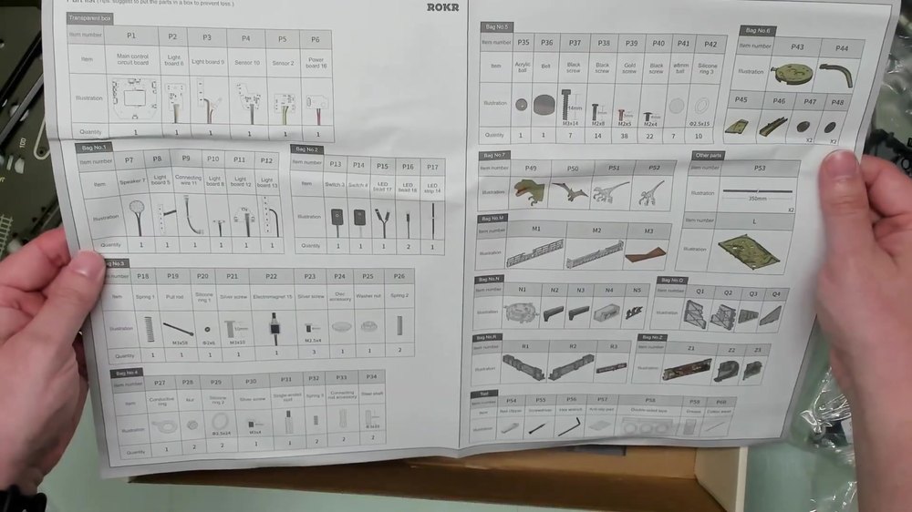
- Before assembly, use the Parts List Sheet to identify the contents of your kit.
Assembly Guide
Stage 1: Ball Return and Trigger Mechanism
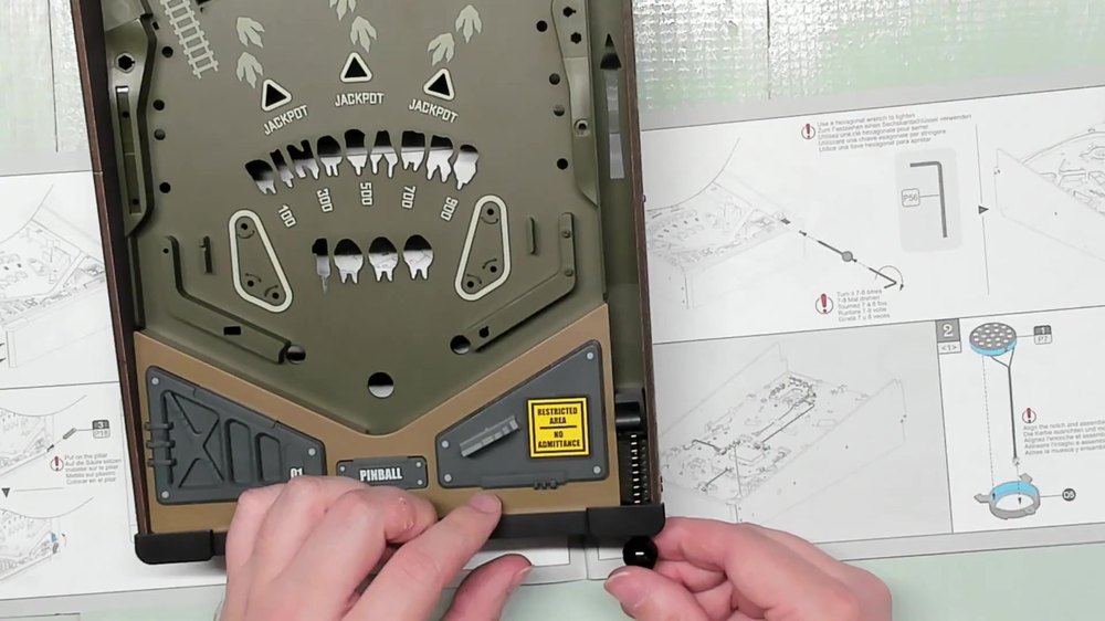
- From Bag 5, take one P41 8 mm ball bearing and press it into its housing until flush.
- Take part A6 and fit it so it slides over a small post and rests on top of the brown piece beneath it. Secure the return arm with a P40 screw from Bag 5.
- Locate part L/R for the playfield panel and fit it over the two mounting posts. Secure with the two P40 screws.
- From sprue Y, cut part Y2. Using three P38 screws, mount the "Dinosaur Lab" Y-side panel by lining up the front post with its matching hole, then driving in three screws. Repeat the same three-screw process for the matching Y-side panel on the opposite side, using the second Y1 piece.
- From bags Q, D, and M, fit M3 into its housing, snap piece Q into place, then press-fit D2. Take Q4 and apply the "Restricted Area / No Admittance" sticker to its face. Take B6 and apply the U14/U15 sticker to it. Press the Q4 assembly into the top of the sticker-B6 piece, then press that assembly into the housing.
- Using the locating holes, fit J7 into its housing, then press the mating piece on top of it. Test the mechanism to ensure it still moves freely and triggers the piece beneath it after seating.
- Secure the base of this section with three P40 screws.
- Fit the Z1 front piece into place and screw down the sides using four P38 screws. Secure Z1 through the holes on each side of the housing.
- Slide the P18 spring onto the plunger pillar. One end hooks over the post at the base, and the rest of the spring housing slides up over it.
- From Bag 3, take the long plunger rod and the P20 washer/gasket. From Bag 5, take the plunger knob and insert the bolt into the smaller-hole side fully, then slide the washer down over the assembly.
- Install and tension the plunger. Slide the rod assembly into the spring housing so it connects to the plastic mechanism at the top. Tighten with the Allen key.
Stage 2: Electronics
- From Bag 1, take part P7 and fit D5 into position.
- Mount the speaker. Unpack the pre-wired speaker from Bag 1. Feed its cable down through the ring opening and align the notch on the speaker housing with the cutout. Press into place.
- Seat and secure the speaker housing. Slide the two housing tabs into their mating slots and press down. Secure with a single P39 screw.
- Expose the connector block. Pop out the plastic protective cover over the main connector strip, revealing the pin connectors.
- For the E-series light panels. From sprue E, cut and fit, in this order:
- E2 — sits at the top, raised triangle side facing down into the housing.
- E1 — the "Dinosaurs" panel.
- E4 — the "1,000" panel into its dedicated slot.
- E3 — the arrow panel into its slot last.
- F3 has a cutout dimple that fits around a locating post, with a notch on the side that clears the green plastic knob nearby. Press into place.
- Align the P2 LED driver board’s two posts with the matching holes. Secure with two screws.
- Using four P39 screws, mount the board above P2.
- Insert the ribbon connector into the bottom port, then press firmly.
- Plug the long P8 LED bar’s connector into the bottommost port on the board. Set the bar over the arrow assembly and secure with two P39 screws.
- Insert the bottom edge of the single-cable connector P9 (Bag 1) first and snap it into place. Lift the adhesive tape strip near the connector, tuck the cable under it, and press the tape back down. Connect the far end to the leftmost of the two remaining ports.
The buttons should now be sitting over their respective LEDs when you flip the assembly, and the ball-return arm from Stage 1 should move freely.

Stage 3: Playfield Bumpers, Solenoid, and Flippers
Section 1: Conductive Ring and Bumper Wiring
- Apply the P27 conductive ring. Find the double-sided P58 adhesive disc and peel the backing off one side carefully. Stick it into the marked slot.
- Find the small M3 screw (P21, in Bag 3) and its matching nut (P28, in Bag 4) and secure loosely for now.
- Separate the black and white wires. Take the black wire, curl it around the screw post from step 2, and tighten the nut down to lock it in place.
Section 2: Bumper Housings
- Identify bumper hardware P29 (a translucent/white post, ×2) and P42 (small silicone O-rings). Fit part A4 (or A1 for the second bumper) into its housing, snap three B4 clips into place around it, then use three P37 screws with the Allen key.
- Wrap the correct P42 silicone O-ring around the groove at the center of the three posts. Repeat the entire section for the second bumper (A1/B4/P37/P42).
Section 3: Bell Assembly
- Take the bell piece (Bag 5) and the large post (Bag 4). Insert the P30 screw into the top of the bell, then thread the post onto it from below until snug.
- Drop the nut into the molded cutout in the playfield and screw the bell assembly down onto it from above until tight.
Section 4: Solenoid
- Attach the solenoid bracket. Locate the solenoid (Bag 3) and part D11 (four holes on one face and two on the other). With the four-hole face down, align the two remaining holes to the side of the solenoid and secure loosely with one P23 screw.
- Flip the assembly so the solenoid sits centered with its guide brace fitted over the locating post. Secure it with two P39 screws (the brass/copper-colored screws).
Section 5: Solenoid Wiring
- Using one P23 screw, attach the white wire to the top hole of the plastic brace that wasn't used in Section 4.
- The solenoid's own cable plugs into the middle connector. Press down firmly. There will be excess cable for now.
Section 6: Support J6/R1 Post
- Turn R1 (sprue J6) so it sits horizontal, then snap it down onto the piece beneath it using the metal nub on top as a guide.
- Punch out the small wrench-shaped tool piece (sheet W2). Take the cup piece (Bag 3), lock washer, lock nut, and washer. Hold R1 steady and screw the cup piece down snug, first by hand, then the rest of the way with the wrench tool.
- H3 has three attachment pegs. Carefully clip it from the bottom of the sprue, leaving the columns and only clipping the leftover connecting joints.
- Fit C8 into the ring on H3.
- Thread the H3/C8 assembly onto R1. Once fully secure, R1 itself can be lifted out and set aside.
- Clip C3 free from the top of the sprue.
- From the sticker sheet, peel one U7 lightning-bolt sticker and apply it to the flat face of C3.
- Unwind the P3 circuit board bundle. With the board's back side facing you, feed the circuit board in diagonally through the marked hole so it sits flush against the adjacent piece for the LEDs to shine through later.
Section 7: "Hearts" LED Panel
- Locate F4, the small panel with X-shaped cutouts. Don’t trim the two raised nubs off when cutting it free from the sprue.
- Feed F4 up through its mounting hole so it presses loosely onto the back of the X-shaped piece, lining up the LEDs. Secure with two P39 screws.
- Route the assembly back down through the board so the X pattern faces the front. You should see silver facing out the back. Secure with a P23 screw.
- From Bag 4, find the P32 springs and part B14. Fit B14 into place, then twist the two P32 springs down onto their mounting pegs on either side to create a spring-loaded switch.
- For the switch assembly, press the spring-loaded piece into place so its two pegs seat into their holes, then hook the free end of each spring over the two screws installed in Section 6 (Step 9, the P3 circuit board screws).
- Feed the wires down through the two holes at the base. Push the piece firmly until no gap remains.
- On the back, feed H10’s cable down through the center hole of the part with mounting pegs, then notch it into its housing.
- Cut the "hearts" panel F1 from its sprue and snap it on top of H10 so it seals shut.
- Flip the assembly and fit the sealed H10/F1 piece into its slot on the completed panel, feeding the wire down through the opening below it.
- Snap the H12 hinge cover (the part with the cutout side) into place over the hearts panel.
Section 8: Right (J1 Side) Flipper
- Take one P36 screw (Bag 3) and part J1 with the "R". Feed the flipper spring down over the long blade-shaped post on J1.
- Using one P39 screw, mount one P33 metal retaining bar (Bag 4), positioning the bar so the circular cutout end sits closer to the mounting slot. Screw it down.
- Fit the J4 flipper arm. With the "R" mark facing up, slide the metal contact so it sits between the two plastic layers, then drop a P39 screw through the mounting hole. Turn it in only halfway at first, slide the arm fully into position, then tighten slowly.
- Route the wires clear of the mounting area, hook the return spring down over the plastic guide post, then insert the small P34 metal pin into the center of the assembly.
- Apply silicone grease to the metal contact points before final assembly. Don't force the final cap piece on dry.
Section 8: Right Flipper (Grease and Final Cap)
- Use silicone grease generously (not excessively) on the flipper pivot’s metal contact piece and both sides of the black plastic arm, applying with the applicator from the tool bag.
- Mount the J5 retaining cap using two P39 screws. The center hole should fit over the greased metal post.
- Using one P39 screw, part P47, and cap P48 (all in Bag 6), attach the flipper knob by screwing P47 onto the flipper shaft, then snap cap P48 over.
- Fit N3 into place, then press the health/star indicator H2 onto it. Secure with one P40 screw, making sure the notch on the shaft lines up with the matching notch inside N3.
- Connect the speaker cable into port 7, and a second nearby wire routes up and over to connect into port 8.
- Add the X1 cable-management clip that fits over this wiring run to keep it seated and out of the way of the moving flipper mechanism.
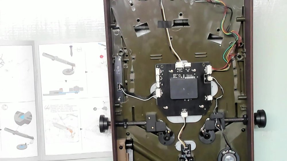
Section 9: Left Flipper (J3 Side)
- Attach the flipper spring. Repeat Section 8, Step 1 using part J3 (marked "L") and the second spring.
- Mount the retaining bar. Same process as Section 8, Step 2, but using a P39 screw and the second P33 metal bar.
- Fit the flipper arm (J2). With "L" facing up, tighten the P39 screw about halfway first, slide the disc into position, then tighten slowly.
Section 9: Left Flipper (Grease and Final Cap)
- Repeat the greasing process on the left flipper's pivot mechanism, following the same method as Section 8.
- Mount the J9 retaining cap the same way as J5, with two P39 screws.
- Attach the flipper knob using the same P39 + P47 + P48 process as the right side.
- Fit the left flipper arm. N2 is the flipper piece with the claw-mark graphic; press H2 down on top of it, then secure from underneath with one P40 screw.
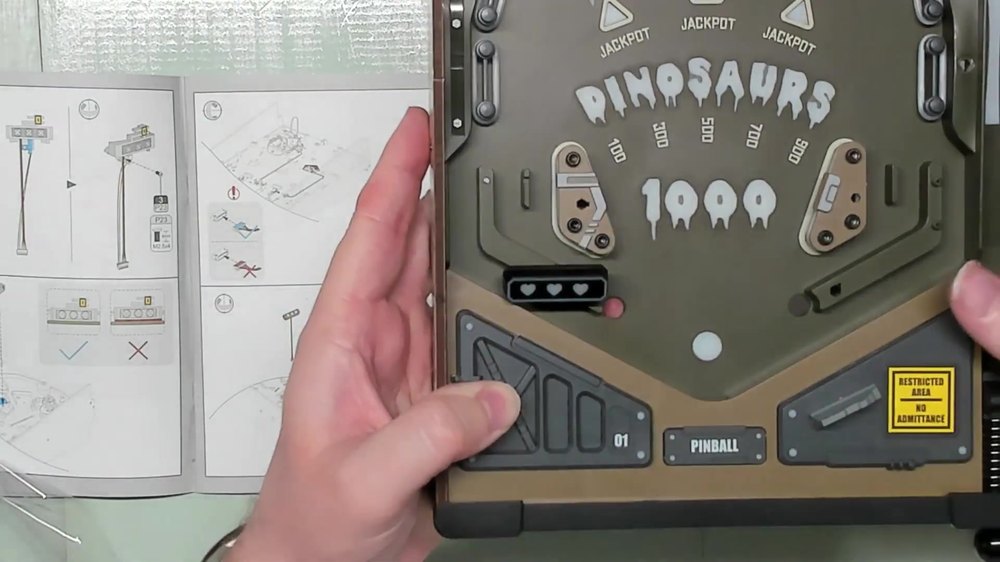
Section 10: Rear Pillar Cap and Connecting Ramp
- Press down H6 onto the rear pillar assembly near the back of the playfield.
- Add the P44 connecting ramp from Bag 6 into a matching slot and hole on H6, plus two posts on the far end that seat into the holes on H6 itself.
Section 11: Central Circuit Assembly
- Snap the N1 and B15 base piece into place in its mounting position.
- Install the P11 triangular sensor board from Bag 1. Feed the wire of its light sensor down through the mounting hole first, then seat the board over its two locating posts. Secure with one P39 screw.
- Install the P4 LED board by gently unraveling its cable, then fitting the board down over the triangular sensor board. Secure with two P39 screws into the marked positions.
- Route both cables under the small gray wire clips by pressing the wires under firmly without bending the clips out of shape.
- Connect both cables to the main board. The longer wire (from the LED board) connects into port 10; the shorter wire (from the triangular sensor board) connects into port 12.
- Secure the assembly with two P40 screws into the two marked positions.
Section 12: Install the additional P46 ramp from Bag 6. Two posts on the underside snap into their matching holes. Secure with one P40 screw driven up from underneath.
Section 13: Loop Ramp and Partial Final Wiring
- Take the Z2 loop ramp and the P5 circuit board (with the two light posts). Fit the board down into its two mounting slots and secure with one P39 screw through the center.
- Route the cable cleanly into the bottom of the built-in Z2 management slot.
- Close the Z3 loop by snapping it into place over Z2.
- Slide B13 in with its holes facing outward and its side grooves engaging the loop assembly.
- Press C4’s posts into the holes on top of the G9 platform.
- Add the F2 warning sign without cutting the small retaining nubs on three points around the inside edge.
- Slide S4 through a center hole without screwing yet. Set this aside.
- Cut H1 and press it into a notch on both the post and the housing until fully seated.
- Feed the assembly's cable into the large slot first on the main board. On the underside, align two posts and a locating lip into their matching holes and snap down, then connect the curved section's two posts to the adjacent piece already on the board.
- Secure with a P40 screw into the mounting hole closest to where the cable exits.
- Connect the final cable into the topmost open port near where it exits.
Stage 4: Ramps and Raptor Cage
Section 14: Ramps
- Fit the wide end's tab into ramp S3’s slot, and the peg at the top into the frontmost hole. Secure with one P40 screw underneath.
- Take S1 and B7 (with the white arrow). Press B7's two posts into the arrow-shaped opening, then connect the near and far ends of the assembly to their mounting points. Don't press on the arrow piece itself once seated, since it can pop back off.
- Press the two holes on either side of C12 onto the pegs on the underside of T2 until snug. Mount the assembled ramp so its gray section connects to the panel.
- Fit the crossing piece B8 across the printed "train track" section, aligning the slot and hole.
- Fit P45 (from Bag 6) on top of the B8 track assembly you just built.
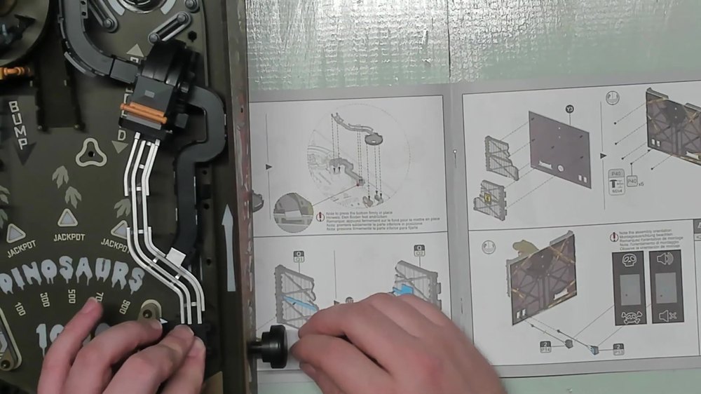
Section 15: Raptor Cage
- Mount the P43 round cage base (from Bag 6) in its marked position.
- U9 sticker wraps around the edge of the cage opening; U10 sticker goes in the adjacent marked spot; U11 sticker is a cross-brace that goes over U9.
- Take the curved H5 cage bar and fit one H8 in the center, then H5 on one side, carefully.
- Apply sticker U12 to B12’s "broken" face. Fit B12 into its single-orientation slot. Repeat with B11 and sticker U13, fitting it into the panel beside the first sign.
- Slide G11 pipe’s square end into the slot on the side of the F5 ROKR sign, then mount the combined piece onto the front of the cage using its two locating posts and holes.
- Cut two A2 base pieces and take the two pre-painted raptor figures from Bag 7. Press each based raptor down into its marked spot inside the cage.
- Add the C5 rock backdrop into place behind the raptors.
- Cut one A3 tree piece, plus K1 and K2. Fit K2 on first, followed by K1 the same way. Fit the assembled tree into its base. Snap the finished tree/cage assembly into its final mounting slot on the playfield.
- Position the completed raptor cage assembly over its three mounting pegs and press down the underside of the G11 pipe.

Finishing Stage 4
- Install the final T1 ramp, the last piece on sprue T.
- Install the S2 funnel. At one end, two closely spaced posts drop into their holes; press fully down. Route the piece along the side of the playfield, connecting at the far end via two more posts, with a flat silver piece (two pegs underneath) capping the connection.
Confirm both flippers still move freely before moving on.
Stage 5: Backboard Assembly
Section 1: Doors and T-Rex Panel
- Cut the door piece Q1 and apply sticker U16 straight down its center.
- Apply stickers U17 and U18 on the outer sections of Q2, and U8 ("Danger Keep Out") across the center.
- On the back face of the large Y3 wood panel, fit the Q1 and Q2 door pieces into their peg positions, one on each side.
- Flip the panel over and drive in six P40 screws (three per door) into the pegs.
- Mount the T-Rex figure through its two holes on the front so it appears to be "bursting through." Secure with two P40 screws.
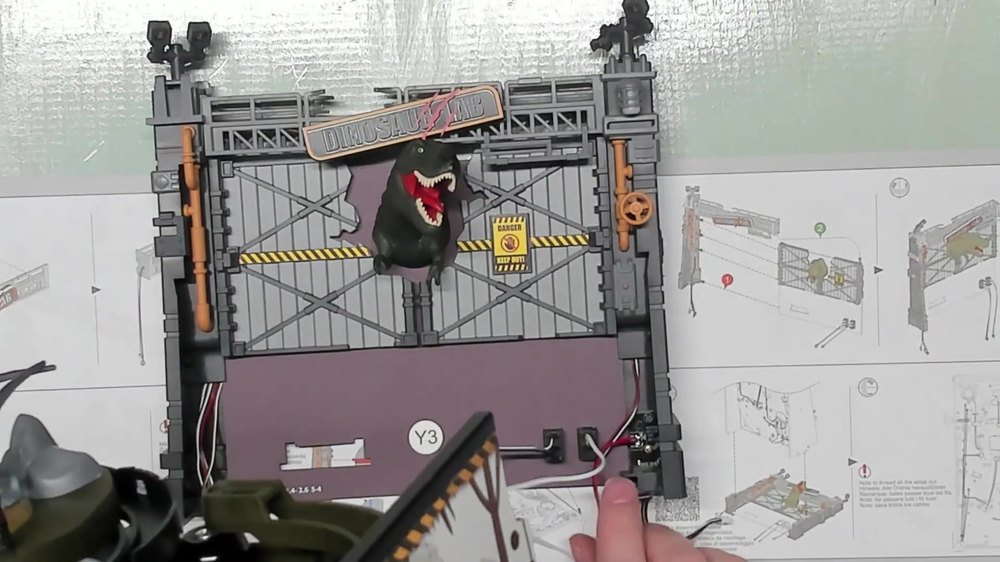
Section 2: Switches (Power and Audio) and Support Pillar
- Feed the P14 power switch (from Bag 2) through its mounting hole with the "open circle" symbol facing up.
- Feed the P13 audio switch (from Bag 2) through with the double-line symbol facing up.
- Fit B2 into a notched hole on R2 to assemble the support pillar.
- Orient G2 with the curved section at the bottom. The straight arm fits into the hole above the B2 red-dot piece, while the curved end's opening slides down over a separate post.
- Press G1 into place and then press the G3 spinning wheel onto the front. It should remain free-spinning.
- Press B5 to the top of the pillar.
- Press-fit C9 above the wheel.
- Press down the overhanging lip of the C14 topmost piece facing the slit in the piece installed just before it.
Section 2: Tower LEDs and Lamp Posts
- Take the main tower LED (red, white, and black wires) from Bag 2. Feed the white LED in from the front through to the top opening, and the red LED through the front-facing hole. Hide the cables in the molded slit, leaving some slack loose near the bottom for now.
- Slide the LED into D9, and cap the D6 lamp housing over it from behind. Pull a little extra LED cable through before capping it.
- On the back of the D1 lamp post is a routing groove for wire. Mount the light facing down. Feed the wire into the groove as you snap the lamp housing into place, then route the wire down through the base.
- Take the "cracked" D7 lamp post and snap it onto the opposite side from D1, angled down.
- Fit F6 into the bottom of B17 using the rear notch that clips around an internal post. This cap then slides over the red LED at the front. Don't force it to avoid crushing the leads.
- Using one P39 screw and part P6 (the small USB-C connector board), fit the USB-C connector board's post into its mounting hole at the base of the tower. Secure with the screw.
Section 3: Second Pillar Assembly and Dual Lamp
- Take the second pillar base G8 and fit its curved section down, with the side tab seating into its hole. Fit G6 between the two holes it bridges.
- Take C10 and press it onto the pillar. Cap the top of the pillar with C13.
- From Bag 2, take two single-LED P16 units. For each, take one D9, one D6, and one D8. Fit each LED into its D9 base, then cap with the correct D6/D8 back piece.
- Mount both lamps onto D3. Press both completed lamp assemblies onto D3's two mounting posts.
- Feed each lamp's cable down through the top of its tab-guided pillar. Don’t confuse the left with the right wire as you route them.
Section 4: LED Strip, Sign Board, and Final Wiring
- Apply four short strips of P58 double-sided tape along the channel of M2 where the LED strip will sit.
- Take the LED strip from Bag 2 and feed it through the hole on one side, routing it up and over the row of pegs so it lies flat across the tape you just placed, then back down the other side.
- Take the small LED PCB P12 (from Bag 1) and feed its wire through the back of the sign board S5.
- Press down the R23 Dino Lab sign over the S5/P12 assembly.
- Position broken cage panel M1 with the broken-cage graphic toward the left. Feed the cable through the central square hole, then snap the panel down over the mounting holes. Route the wire tightly up and around the designated post at the back.
- Mount M1 upside-down onto the tower. Feed the Dino Lab board's wire through the side hole and press the assembly into place.
- The C15 piece hangs down into a slot and tucks under a nearby lip.
- Align the two tower half section posts, making sure both sets of pillar cables are routed down the same side before pressing the halves together.
- Use sticker U14 to wrap and bundle the cables where they exit the base.
- Snap on each final side panel post to the holes, minding your bundled cables as you press them into place.
- Run each plastic edge rail down the full length of the table edge, starting from the side with a printed graphic and towards the back.
- Set the completed tower in place, threading all wires out cleanly before securing to the table. Fasten with one P38 screw on the outside marked "X" and one P39 screw driven internally on each side.
- Connect all cables per the wiring diagram. Match each connector by wire color/count to its labeled port on the main board: the double-white wire goes to the top port (P4); the second switch's white/black/blue wire goes to port 3 on the central board; the 4-wire connector (shorter cable, right side) goes to port 17; the red/black pair goes to port 16; the two white/black wires go to ports 18 and 19; the brown/red pair goes to port 14; and the white/brown pair goes to port 13 on the bottom PCB. Confirm no port is left unconnected once finished.
- From sprue X, cut seven X1 clips and press them into their marked positions along the base and center of the board to keep the bundled wiring tidy and out of the way of moving parts.
Ball Storage Carriage
- Punch and assemble the carriage frame (W5, W6, W10). Printed/black sides face up and out; W10's side tabs feed into the matching holes on W5 and W6.
- With the black side up and tabs front and back, press the W3 main housing firmly along each edge.
- The W12 back panel fits along the back the same way, then the swinging feed-through gate feeds in from behind and pushes through until it pops out the front.
- Black side out, cutout facing up; lift the rotating flap to slide the W4 front gate into place, then let it drop flush.
- Load the P41 spare balls into the individual holes in the carriage. Close the cover over them and slide the carriage back into the housing to lock them in.
Stage 6: Final Assembly, Signage, and Base
Section 1: Spinning Sign, Base Frame and Feet
- Apply sticker U2 to both faces of the spinning H11 triangle sign. Fit a P42 O-ring around the grooved base from underneath, then mount the sign at the center. Secure from below with one P40 screw.
- Assemble the corner bracing (W1, A7, A5). Using two P39 screws, attach corner pieces A7 and A5 into their respective notched corners from the back of W1.
- Mount the bracing to the table. Fit the W1/A7/A5 assembly into the center bracing area on the underside of the table, watching that no wires get pinched, then secure with two P38 screws.
- Punch two V1, two V2, and one V3 from the punch board. The V2 pair fits into one set of marked slots, V1 divider pieces go into the side slots, and V3 sits perpendicular at the back.
- Attach the W1 bottom panel and secure with six P39 screws.
- Press four P57 feet into the marked cutouts on the bottom panel.
Section 2: T-Rex Sign, Crates and Landscaping
- Orient B10 so its posts face the front, then slide the H4 T-Rex sign into the top slots.
- Build the first crate (G7 + G5). Fit G7 with its open face toward you, snap G5 on top, and slide the door down on the crate. It should be half-open.
- Build the second crate (B9 + C6 + N4). Snap C6 on top of B9, then insert door N4 only about halfway, matching the first crate. Stack the two crates together with the first crate on the bottom, the second on top.
- Build the second palm tree using parts A3 + K1 + K2.
- Apply sticker U4 (a lowercase "stop") to one face only of the upside-down H7 stop sign.
- Seat the stop sign in its marked slot, add the row of soldier figures (Bag N), place the second palm tree directly in front of the soldiers, and mount the T-Rex sign directly in front of the T-Rex figure. Then fit the stacked crates into their marked slot.
Section 3: Remaining Signage and Final Details
- Apply sticker U6 to one face of C7.
- Snap C2 onto the back of C1, then press the assembled informational sign into its stand.
- Apply sticker U5 to both faces of B1 to build the knot sign.
- Apply sticker U3 slowly to the broken H9 sign.
- Place the final details on the board, in order: the B3 "Keep Out" sign along the edge of the marble-swirl feature; the G10 barrel into its notched slot beside it; the broken-H9 "60" sign into its own notched slot; B16 beside the 60-sign; C11 behind that; the signpost base into its slot; and finally the B1 knot sign snapped onto the signpost's two posts so it can still spin freely.
- Mount the pterodactyl (Bag 7) onto the top of the orange signpost assembly.

A Word from ROKR
Thank you for trusting ROKR. We hope this assembly guide has helped you build your Dinosaur Lab Pinball Machine MGP01 successfully.
Please be reminded that the most accurate source of build information is the illustrated instruction manual that comes with your kit.
For questions and part replacements regarding this product, email us at service@rokronline.com.